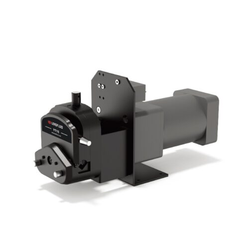
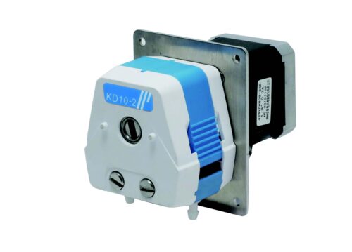
Description
Introduction
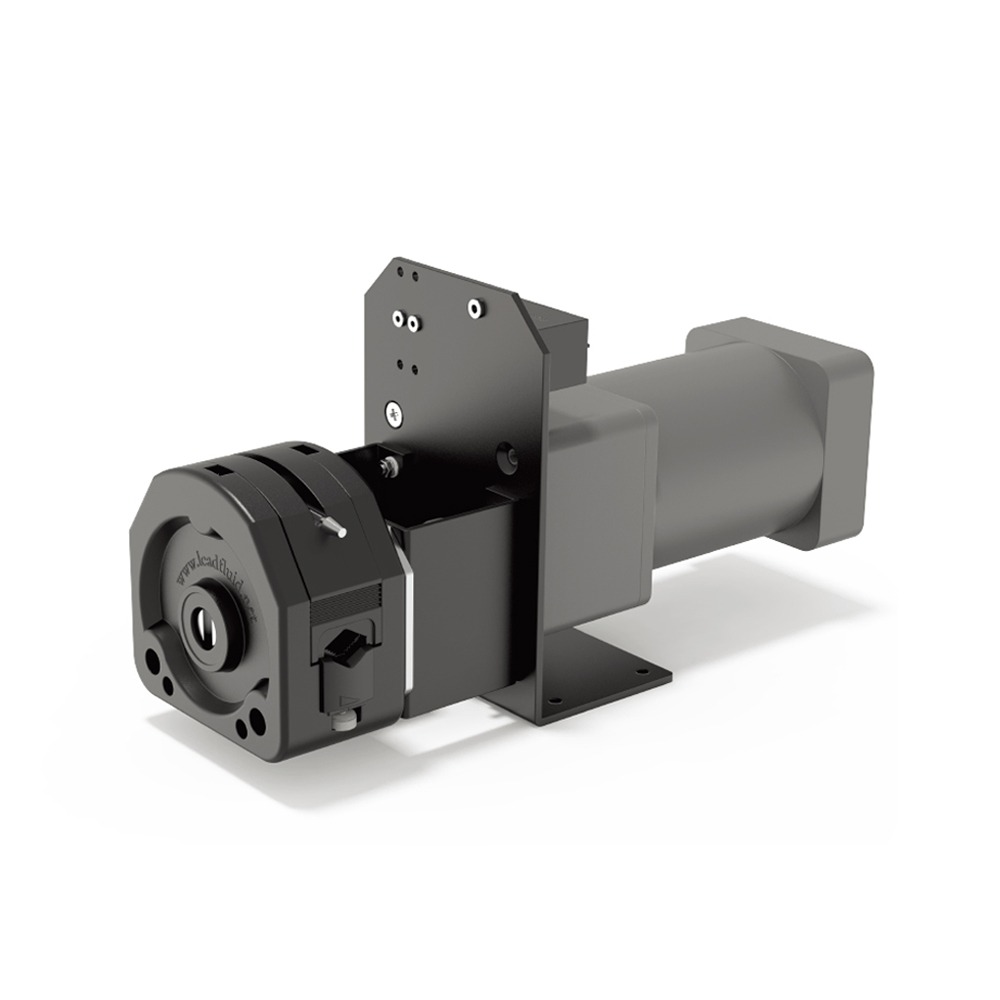
• The KZ25 pump head has a larger transmission flow rate, up to 5.3 L/min.
• Suitable for tubes of various sizes, easy and quick to replace and install tubes
• The rollers are made of stainless steel 304 and are suitable for different working conditions.
• AC reduction motor, cost-effective.
Parameters
Motor Type: AC reduction motor
Power Supply: AC 220V
Wattage: 90W
Fixed Speed: 490±5%rpm
Channel Number: 1
Number of Rollers: 3 rollers
Rotation Direction: Clockwise/Counterclockwise rotation
Lift Head: 10 m
Adaptable Tube Wall Thickness: 2.4 mm
Suitable Tube (ID): 15#(4.8mm), 24#(6.4mm), 35#(7.9mm), 36#(9.6mm)
Material of Tube: Silicone, Pharmed
Method of Tube Installation: Fixed by pump head
Pressure Tube Type: Pump head tube clamp
Pump Head Shell Material: PPS
Pump Head Roller Material: 304 stainless steel
Pump Head Life: ≥5000h
Noise: ≤85dB (test environment noise ≤40dB, test product and noise meter horizontal distance of 1 meter)
Weight: 7kg (without tube)
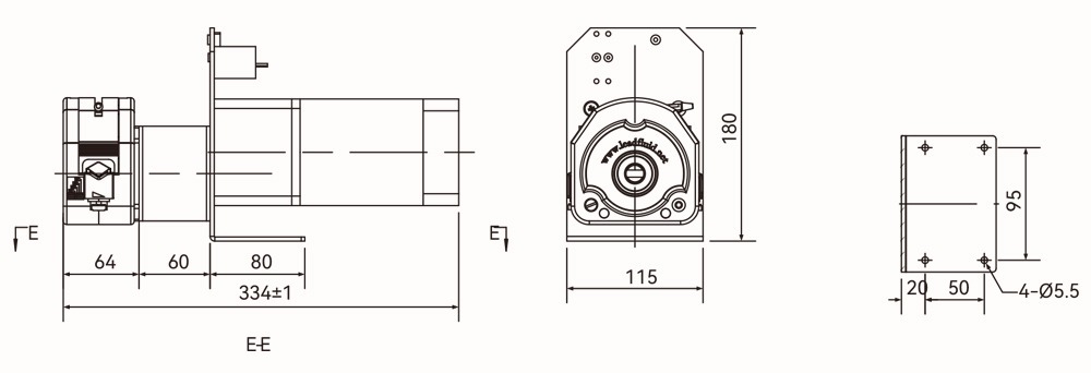
Dimensions: (L×W×H) 334*115*180(mm)
Working Environment: Temperature 0- 40°C, relative humidity<85% RH
Storage Environment: Ambient temperature of -20 ~ +50 °C, relative humidity of not more than 95% of the clean and well-ventilated environment, the air shall not contain corrosive, flammable gases, oil mist, dust.
Flow Rate Reference Table
| Tube ID(mm) | 15#(ID4.8) | 24#(ID6.4) | 35#(ID7.9) | 36#(ID9.6) |
| Flow Rate (mL/min) | 1519 | 2597 | 3773 | 5390 |
The above data is obtained from the test of purified water with a Lead Fluid tube under normal and pressure conditions in the laboratory. This data is for reference only.
Due to pressure in actual use, temperature, medium characteristics, tube material and other specific factors, the specific situation needs to consult our engineers.
Product Structure & Usage Method
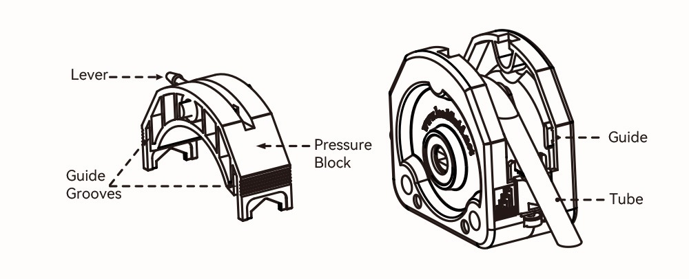
Product Structure
Tube Installation
• Rotate the pressure block lever 180° counterclockwise, lift up the pressure block to remove the pressure block.
• Place the tube on the rollers and the V-grooves of the tube clamps on the left and right sides.
Usage Method
• Restoration Pressure Block. First, align the rotating shaft of the pressure block with the gap on the upper part of the front and rear shell. Place the pressure block into the shell along the guide grooves of the front and rear.
Then press the pressure block with one hand and use the other hand to hold the pressure block. Rotate the lever 180° clockwise by hand to lock the pressure block.
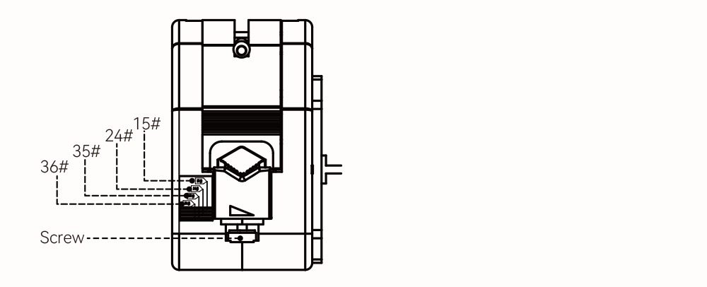
• According to the thickness of the tube, turn the screw under the tube clamp (Note: The triangle on the tube clamp is the direction mark) to clamp the tube.
Dimension
unit: mm
